Cyclone Pcb Factory
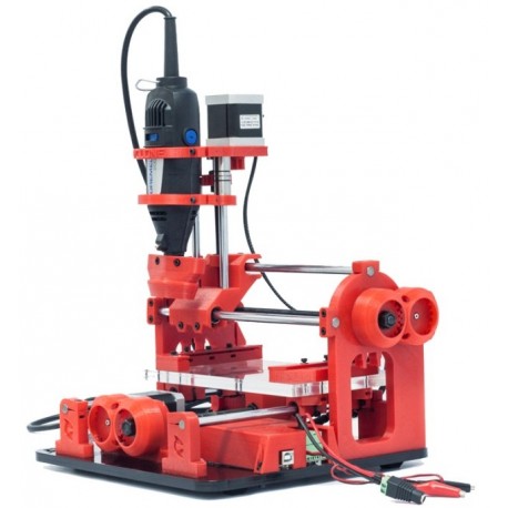
The aim of this tutorial is showing how to configure a Cyclone PCB factory.
First steps
The main circuit to control the CNC is an Arduino with an Arduino CNC Shield.
Arduino CNC Shield
The Arduino CNC Shield makes it easy to get your CNC projects up and running in a few hours. It uses opensource firmware on Arduino to control 4 stepper motors using 4 A4988 Stepper drivers, with this shield and one Arduino.
Jumper Settings
Jumpers are used to configure the 4th Axis, Micro stepping and endstop configuration. The next few sections explains how its done.
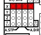
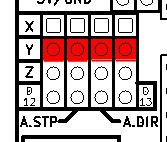
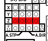
4th Axis Configuration
Using two jumpers the 4th axis can be configured to clone the X or Y or Z axis. It can also run as an individual axis by using Digital Pin 12 for Stepping signal and Digital Pin 13 as direction signal. (GRBL only supports 3 axis’s at the moment)
Clone X-Axis to the 4th stepper driver.
Clone Y-Axis to the 4th stepper driver.
Clone Z-Axis to the 4th stepper driver.
Use D12 and D13 to drive the 4th stepper driver.
End Stop Configuration
By default GRBL is configured to trigger an alert if an end-stop goes low(Gets grounded). On the forums this has been much debated and some people requested to have active High end-stops. The jumpers in the picture provides the option to do both. (To run with default setting on GRBL the jumper need to be connected like the left shield in the image below)(This Jumper was only introduced in Version 3.02)
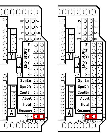
End-stop switches are standard “always open” switches. An End-stop gets activated when the end-stop pin connects to ground(When setup with default GRBL settings).
Configuring Micro Stepping for Each Axis
Each axis has 3 jumpers that can be set to configure the micro stepping for the axis.
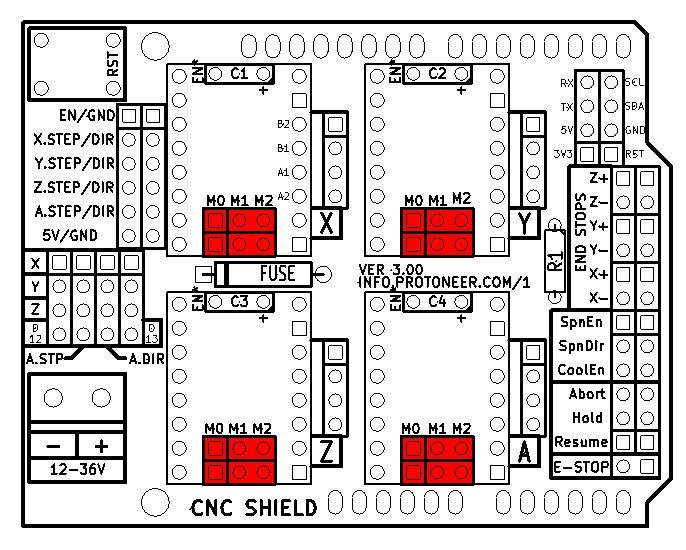
In the tables below High indicates that a Jumper is insert and Low indicates that no jumper is inserted.
Pololu A4988 Stepper Driver configuration:
| MS0 | MS1 | MS2 | Microstep Resolution |
|---|---|---|---|
| Low | Low | Low | Full step |
| High | Low | Low | Half step |
| Low | High | Low | Quarter step |
| High | High | Low | Eighth step |
| High | High | High | Sixteenth step |
Pololu DRV8825 Stepper Driver configuration:
| MODE0 | MODE1 | MODE2 | Microstep Resolution |
|---|---|---|---|
| Low | Low | Low | Full step |
| High | Low | Low | Half step |
| Low | High | Low | 1/4 step |
| High | High | Low | 1/8 step |
| Low | Low | High | 1/16 step |
| High | Low | High | 1/32 step |
| Low | High | High | 1/32 step |
| High | High | High | 1/32 step |
GRBL Configuration
Grbl is a no-compromise, high performance, low cost alternative to parallel-port-based motion control for CNC milling. This version of Grbl runs on an Arduino with a 328p processor (Uno, Duemilanove, Nano, Micro, etc).
The controller is written in highly optimized C utilizing every clever feature of the AVR-chips to achieve precise timing and asynchronous operation. It is able to maintain up to 30kHz of stable, jitter free control pulses.
It accepts standards-compliant g-code and has been tested with the output of several CAM tools with no problems. Arcs, circles and helical motion are fully supported, as well as, all other primary g-code commands. Macro functions, variables, and most canned cycles are not supported, but we think GUIs can do a much better job at translating them into straight g-code anyhow.
$100, $101 and $102 – [X,Y,Z] steps/mm
Grbl needs to know how far each step will take the tool in reality. To calculate steps/mm for an axis of your machine you need to know:
- The mm traveled per revolution of your stepper motor. This is dependent on your belt drive gears or lead screw pitch.
- The full steps per revolution of your steppers (typically 200 for NEMA 17 Stepper motor)
- The microsteps per step of your controller (typically 1, 2, 4, 8, or 16). Tip: Using high microstep values (e.g., 16) can reduce your stepper motor torque, so use the lowest that gives you the desired axis resolution and comfortable running properties.
- A 8mm diameter rod has a 1.25mm step. That means each rotations the axis moves 1.25mm.
- Gearbox acceleration factor shows the speed increment donde by the gearbox.
The steps/mm can then be calculated like this: steps_per_mm = (steps_per_revolution * microsteps * Gearbox acceleration factor)/mm_per_rev
Compute this value for every axis and write these settings to Grbl. In my case:
- X axis = 200 * 16 / 1.25 = 2560
- y axis = 200 * 16 / 1.25 = 2560
- z axis = (200 * 16 * (8 / 15))/ 1.25 = 1365